
The Tivoli Audio Model One AM/FM table radio has been described as “the best sounding table radio ever made,” offering “the kind of room-filling sound that many other radios claim to deliver but often don’t.”
A heavy magnet, long throw driver is mated to a frequency contouring circuit that automatically adjust output over half-octave increments, resulting in musically accurate tonal balance and bass response. “When your stereophile loved ones turn the knob on this rock solid Henry Kloss Model One Table Radio, they’ll cry with hi-fi joy”

The first series of Model One had a source selector at the front for only FM and AM radio. The radio however had an AUX input (mini jack) at the back. By connecting the AUX cable it would override the FM/AM signal to the amplifier. The only way to select radio as a source was by unplugging the mini jack from the back. Later versions added a AUX selection at the front. Now you could leave your AUX mini jack plugged in and select the source at the front.
Owning a first series Model One MK1, that still works excellent, I wanted to modify the radio adding a bluetooth module. This module would be the switching unit: bluetooth selected on a streaming device to stream music to the Tivoli radio. Switching off Bluetooth on the streaming device would give FM / AM. No more jack plugs to unplug.
The board that is needed can be sourced from various sellers. This actual board is Bluetooth 5 version. Cost for these boards is around $15. The board is actually nicely made and comes with all necessary wires.

First thing is to dis-assemble the radio. Remove the 6 screws at the back. Front and back panel is connected with wire ribbons. After removing the screws slowly pull the front out. The front needs to be pulled out & rotate anti-clockwise. At same time you need to rotate so the front faces up. When correctly done you now can slide the front panel through the housing while taking the back out.
The main PCBA layout of your Model One should look like this. Picture is showing the PCBA with modification.
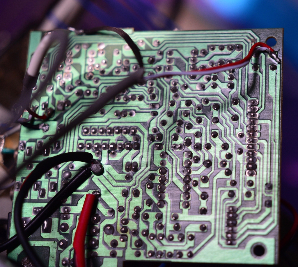
Next step is to locate the AUX connector on the PCBA board. This AUX connector is of a switching type as explained earlier.

The radio signal is flowing through to amplifier via pin 2 and 4 when no jack is plugged in to pin 3 and 5. If jack is plugged in two contacts 2 and 4 inside the AUX connector are disconnected, cutting the radio signal out. The mini jack signal has now priority, signal flows via pin 3 and 5 to the amplifier.
Connect line-out of the Bluetooth module to the AUX connector as per picture

The radio signal needs to be connected to the line-in of the bluetooth PCBA connector. It is necessary to cut the radio signal track on PCBA leading into the AUX. Not doing so will destroy you Bluetooth module. Below pictures shows the red wire and you see just above this wire the copper track is cut.


Once the Line-In and Line-Out wires are correctly attached, next step is to find the necessary power to feed the Bluetooth module. 12V DC can be picked from the main condensator on the DC side. Of course you can also decide to use a separate 12V DC power supply.

A small metal bracket to mount the Bluetooth module and the main PCBA together. The Radio can now be assembled again. Be careful mounting the rear module. The Bluetooth module just fits in the wooden housing. You do not need an additional bluetooth antenna.

Warning: As for all modifications: Assume you are familiar with PCBA, soldering and general safety aspects when working on electrical appliances. Disconnect always from mains before you start.
The AUX mini jack at the back can’t be used anymore after this modification.

Thanks for this post Marcel. I have an original Model One and haven’t been using it much lately, and this would be a good upgrade for me. Could you indicate the maker/part number of the Bluetooth board you used? Thanks
LikeLike
Hi, thanks for reaching out. The board you can buy on Ebay for around gbp 15.00. Search for:
JC-303 Bluetooth DAC Board BT5.0 Audio Receiver Board White w/o Antenna Kit tps
It works very well and gives this superb sounding radio a nice new purpose.
Good luck.
Marcel
LikeLike
This is great. I was going to put my Model One on eBay, but then thought, “I wonder if I could bluetooth this thing?” and I found you. I do have a question though: How do you pair it? Isn’t there some button you’d need to push?
LikeLike
Hi Mark, you can pair on your I pad/Iphone or tablet. Go in to bluetooth setting and the name of the board will appear. Once selected you can stream your music from iPhone/Ipad to the Tivoli. If you switch off your bluetooth it goes back to radio. Let me know if you have any problem. Good luck!
LikeLike
Oh OK. I assumed that like other BT products, you’d have to tell it to go into pairing mode so it appears on your phone as an option, like many BT speakers require you to do. So that’s not the case with this board then? I ordered the same board from ebay, and it looks like it’s going to be a while since it’s coming from hong kong.
LikeLike
Hi Mark,
When the board is activated a name will appear under the bluetooth setting on your Iphone or tablet.
Once selected, the board will switch the normal input (radio) to Bluetooth signal from your phone.
If you switch it off on your phone under bluetooth setting, the radio signal gets priority again. So you will hear the radio. Very simple and most effective.
The board will indeed take a while but still reasonably fast. Let me know if things need clarification. Good luck!
LikeLike
I just finished up this mod, and it’s working great except for one thing, which may or may not indicate an issue. When I first pair it, there’s a bit of “static” where it cuts out for a second. Is that normal? I noticed the blue light on the board flickers off for a second. Other than that, all good! Incidentally will it harm anything if someone did inadvertently plug something into the aux?
LikeLike
PS – where did you hang the bracket inside? Thanks!
LikeLike
Hi Mark, well done. Nothing to worry about. There is a relay on the board that is activated. The Line-In is cut out and priority is then given to the bluetooth. Connecting the PCBA with a dedicated power supply might help, but I wanted to avoid that.
Connecting AUX: In this case DO NOT connect something to the AUX. It will damage the bluetooth module.
Last picture shows a small L bracket with 90 bend and 2 holes. It is screwed together with main board. On the flat top surface a small hole where I screw the BT board onto. It still goes all inside the housing. Bit of creativity and you will find a place to mount. Just make sure it doesn’t touch other components.
LikeLike
Thanks. I plugged the aux port with a bit of epoxy putty. I ended up using a bit of double sided padded adhesive tape to mount it vertically to the back wall on the right. Crazy how much wire is wrapped around the plastic supports inside. Works great! Thanks again for putting this out there!
LikeLike
The wires are AM/FM antenna’s 🙂 hence they will pick up some interference when you switch. Using FM antenna connected on the outside and set the antenna switch correctly might reduce the switching interference also.
LikeLike
I assumed that’s what they were — but usually they’re a little more…precise?..than that. At least in other antique tube radios I’ve repaired. Usually spaced exactly and glued to some sort of backing material. Hey, if it works, I’m not complaining. 🙂 Thanks again!
LikeLike
Got mine installed yesterday, works great! Hardest part is getting front and back panels in the cabinet. I had to trim back the insulation on one of the cables in order to reach the nearest ground, but all and all, it went, well.
Thanks for documenting this.
LikeLike
Hello Marcel,
Thank you for posting this hack! I have a model 2 and I wonder if this modification will work as it does for the model 1. I love this radio and it would be great if I (really my boyfriend) can modify it.
Thank you!
LikeLike
Hi, In principle it should work but I have not the schematics of Model 2.
The main difference between Model 1 is that Model 2 has a dedicated AUX input. (for CD or to connect your phone via cable)
You could connect also a bluetooth module to the aux, if you want to stream music via bluetooth. There are other modules you can buy for that instance. Still you can select radio via the front knob without disconnecting that module.
Model 1 did not have that AUX. Hence it was only possible to do it in the way as described.
And indeed these radios have a fab sound.
Hope it helps.
Marcel
LikeLike
Thank you for the response. I didn’t consider a bluetooth adaptor for the aux input! It’ll certainly be easier than opening up the radio. I’m looking forward to using my radio again.
LikeLike
Bonjour Marcel,
Thanks for the tutorial, great work, really appreciate it. I a proud owner of 2 Tivoli radios, the above Model One and the iPal. I was wondering if modifying the iPal adding a bluetooth module would be possible?
It seems that the PCBA is different from the Model One. I have never done any electronic soldering.
I can share pictures of the iPal PCBA if needed.
Thanks,
Arnaud
LikeLike
Hi Arnaud. Thank you for reaching out. From what I can see, the principle is the same. There is a jack-in at the back that will switch off the source radio, when you plug in a mini jack.
You can send me pictures, but can’t promise that I have all answers. I will have a look however. Marcel
LikeLike
Thanks so much for the clear and cogent directions! I have an adjacent question: I have a MOdel One with BT, but it seems the board is dying. It’s getting DC volts, but no more “beep” to signal connection and the playback is extremely quiet and static-ey.
Given that I already have the circuitry to interface BT, can you recommend a replacement board that would interface cleanly with the existing ribbon connector? Tivoli doesn’t sell replacements and I’d love to use the existing parts as-is if possible….
Many thanks!
LikeLike
I sent you a separate email.
Marcel
LikeLike